Friday, March 21, 2008
So what have I done wrong here?
I am not sure what I have done wrong. Checking against the plans all seems correct, but there is a problem.

If you put the rudder full right, the left hand rudder cable rides under the rudder stop.
As the rudder moves back towards the centre it rides under the stop, but when the cable changes to the SS cable end it can hang up.It can be quite a bit more extreme than shown in this picture.

Here it is just sticking on the edge of the rudder stop. A panicked jab on the rudder pedal will clear it, but I don't like panic in an aeroplane.

Here you see the rudder centralised.

Read more »
Thursday, January 24, 2008
Now it is complete and painted.

It is fiddly work bolting the back end together. Despite having carefully adjusted all the hinges one appeared never to have been locked. In the painting process it had rotated so it was back to a bit of string to ensure everything was in complete alignment.
The Trutrak servo adds some drag to the system, but checking with other users they all say you cant feel it in the air. Other than that everything swings freely.
It is mind numbing work doing all the bolts up one flat at a time. Remember to surround the holes with masking tape so you don't chip the paint.

 The pivot line is very close to the tube. I had to use a metal lock nut there. They are smaller.
Since I don't want to take the inspection panel off too often I thought a split pin might be appropriate here, though VANS are happy with just a Nylock.

Read more »
Saturday, August 18, 2007
The back end is complete.
 Over the last few days I have completed the last few jobs to finish the back end. Hopefully this is the last time I will assemble it before painting. It takes about 3 hours to install and tighten the 4 bolts that hold the front edge of the HS on. A very small child is necessary!
There is not a lot to say of note.
 The VANS empenage fairing I think was perhaps designed for a Eurofighter so did not fit well on an RV4. I have ditched it in disgust and made my own. I found it quite difficult, and it reminded me why I don't work in fiberglass. its not structural fortunately since there is a lot of filler in there. But it does fit around the VS and HS. Its not quite complete but will look OK when I tidy it up.
 There is no way I could attach Adel clamps directly to the longeron to hold the rudder cable in the correct position. I made up these little brackets. In this picture the clamp is swung out of the way and the poly tube pulled over to the left. I think you probably get the idea though.
Monday, January 01, 2007
Aligning the elevators.
 I have set the elevators up in trail in anticipation of drilling the hole in the horn that will lock them together as one. I have done this in two ways:

- i) I aligned them at the front with the HS.
ii) It occurred to me that there is a point on the center line of the aircraft that both elevator trailing edges point to when they are aligned.
The tip of piano hinge in the pictures, is that point. Clearly both methods should give the same result, and it seems they do, but this second method seems to ensure that it is least likely that there is any aerodynamic contradiction between the two.
I am now only bothered as to how to drill the elevator horns, so when it is all bolted up tight, they remain in this relative position.
Labels: HS elevators
Sunday, December 31, 2006
Fitting the elevators
 I have put the elevators on and off more times than I care to remember in the last few days. Sometimes I get the bolts in quite easily, other times it takes 10 minutes per bolt. The good news for me is that it is finally all coming together. I have shaved the HS skin until I finally have just more than the minimums, for elevator deflection. The lead is installed.
Because I have the heavier gauge elevator skins, there is quite a bit more lead back there than I expected. You pay the weight penalty twice. The first time the weight of the heavier skin, the second time the lead to balance it. This left tip is stuffed with lead to balance the extra weight of the trim tab and motor. After it is painted I will be able to drill some lead out of the inner face since it is currently nose heavy.
 At the risk of embarasssing myself I will post another picture, but it leaves no doubt as to my untidyness!
It is not a big issue, but once again the quality of the fiberglass mouldings is a little disapointing; air pockets in the glass covered in gelcoat, and on one of them, the upper and lower half of the fairing are poorly aligned.
Labels: HS Elevators weight
Saturday, December 16, 2006
Vertical Stab.
 Setting up the empenage has proved quite challenging. The issues have been to ensure clearance between the leading edge of the fin and the top of the fuselage.
 I cant see why I have this problem since I have remeasured everything and all seems to be correct. Perhaps everyone runs into this issue.
As you can see I have put some gaffer tape there to resist abraision while I work.
Preserving the necessary edge distances on all the bolts has also been demanding, but we are getting there. The next job is to make the dreaded bend in the top of the HS-410. I think this will need a shim as discussed in the build book.
Despite these difficulties it all appears to be square to within o.1 degree so I guess I should be happy!
Thursday, December 14, 2006
Bending the HS-410

If you follow the build instructions from VANS you arrive at this stage before you bend the HS-410. (The bit with the letter 'H' on in the middle of the picture.) It connects to the forward spar of the VS. Ideally you would bend it approximately to fit before you assembled the HS skeleton.
Now the problem is to hold the HS spar without stressing it, while you make the bend. I will post a picture of what I intend to do when I am all set up.
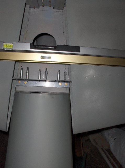
Thursday, August 03, 2006
Ray Allen Trim Servo
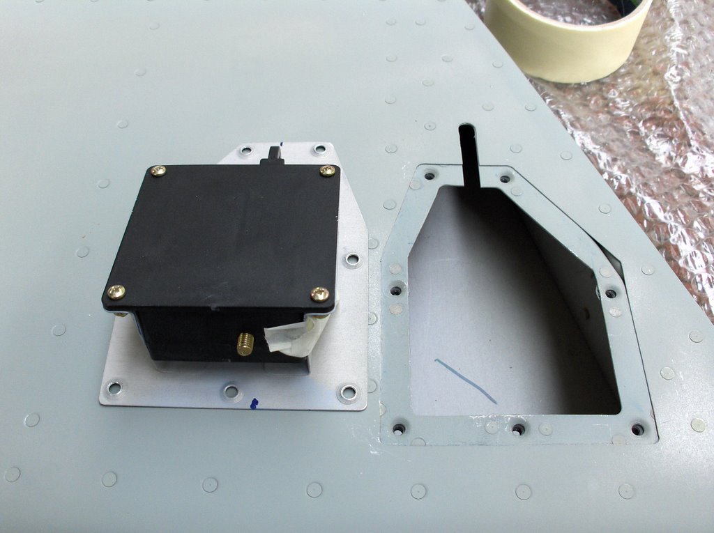 It is time to install the Ray Allen Trim Servo into the empennage.
The last time I did this, when I built an RV9A, I got in a real tangle as to how to get the motor unit in and out of the hole it fits in.
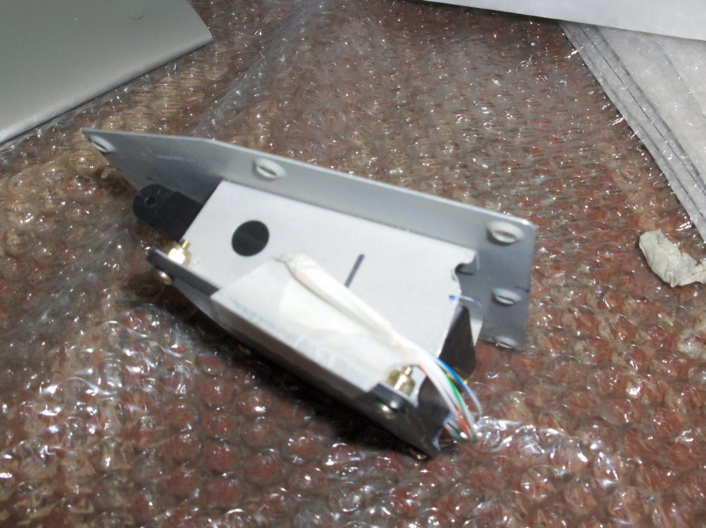 This time I cut a strategic part of the support bracket away. You can just see it in the second picture. It is about half way between the bottom of the servo and the base plate. This small modification, together with a chamfering of the diagonally opposite corner beside the bolthead, made entry and exit easy. It seems obvious to me this time, but it was not the last time I did it!

Tuesday, August 01, 2006
Attaching the Horizontal Stab. (HS)
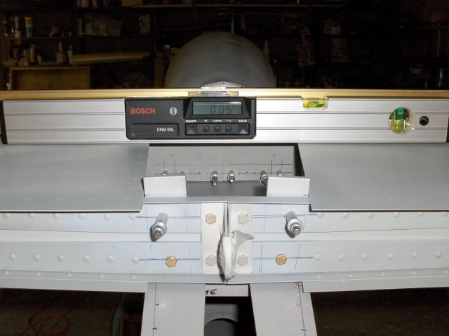
This is where the day ended, with the HS attached to the fuselage with enough AN3 bolts in place for me to be sure nothing is going to move in the night. The good news is on the digital level. Call me slapdash, but I can accept 1/20th degree of error!
The incidence of the HS is similarly accurate wrt the cockpit rails.

Here is the view from above. You might notice the bolt heads are pretty close back to the web.I will come back to that in a moment.
We spent the whole day on the task because issues of edge distance were quite troubling. It is quite impossible to fully meet all of the rules.

In this picture you can see the outer attach holes are placed slightly inboard of the ideal location on the longeron. The reason for this becomes clear in the next picture.
Another point to notice here is the bolt holes are slightly forward of the centerline on the cross piece.

This picture might be confusing at first. The camera is inside the fuselage pointing vertically up. If the holes in the longeron had been further outboard, they would have been located too near the ends of the cross member. (In retrospect this could perhaps have been made minutely longer, but I am happy all is well.)
One thing none of the pictures show, though the third hints at it, is that the two cross angles to be bolted together, one on the HS the other across the fuse' did not line up vertically above each other. I have re measured every dimension and can see no error. VANS expect any misalignment to result in the upper angle being behind the lower one. In my case it was nearly 1/8" forward. This is the reason for the bolt holes being forward on one cross piece and back on the other.
![]()