Thursday, August 03, 2006
Ray Allen Trim Servo
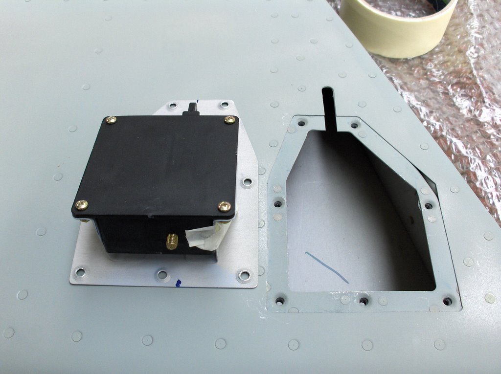 It is time to install the Ray Allen Trim Servo into the empennage.
The last time I did this, when I built an RV9A, I got in a real tangle as to how to get the motor unit in and out of the hole it fits in.
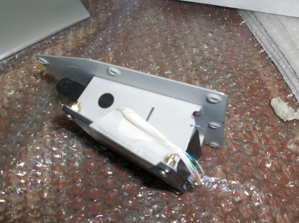 This time I cut a strategic part of the support bracket away. You can just see it in the second picture. It is about half way between the bottom of the servo and the base plate. This small modification, together with a chamfering of the diagonally opposite corner beside the bolthead, made entry and exit easy. It seems obvious to me this time, but it was not the last time I did it!

Tuesday, August 01, 2006
Attaching the Horizontal Stab. (HS)
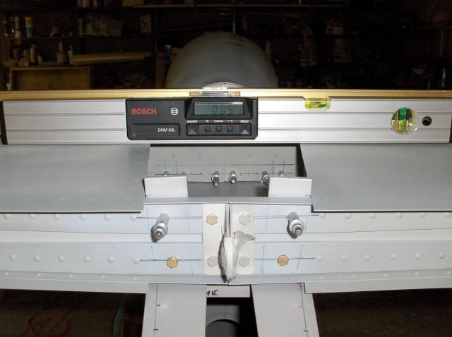
This is where the day ended, with the HS attached to the fuselage with enough AN3 bolts in place for me to be sure nothing is going to move in the night. The good news is on the digital level. Call me slapdash, but I can accept 1/20th degree of error!
The incidence of the HS is similarly accurate wrt the cockpit rails.
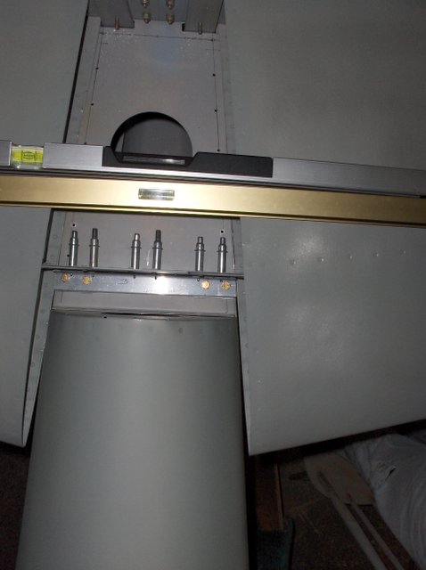

Here is the view from above. You might notice the bolt heads are pretty close back to the web.I will come back to that in a moment.
We spent the whole day on the task because issues of edge distance were quite troubling. It is quite impossible to fully meet all of the rules.

In this picture you can see the outer attach holes are placed slightly inboard of the ideal location on the longeron. The reason for this becomes clear in the next picture.
Another point to notice here is the bolt holes are slightly forward of the centerline on the cross piece.

This picture might be confusing at first. The camera is inside the fuselage pointing vertically up. If the holes in the longeron had been further outboard, they would have been located too near the ends of the cross member. (In retrospect this could perhaps have been made minutely longer, but I am happy all is well.)
One thing none of the pictures show, though the third hints at it, is that the two cross angles to be bolted together, one on the HS the other across the fuse' did not line up vertically above each other. I have re measured every dimension and can see no error. VANS expect any misalignment to result in the upper angle being behind the lower one. In my case it was nearly 1/8" forward. This is the reason for the bolt holes being forward on one cross piece and back on the other.
![]()